The O2 chassis provides an affordable, high-performance graphic workstation, suitable for many of today's most demanding tasks.
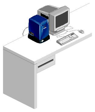
Silicon Graphics O2 systems are designed to be located on a desktop. Figure 3-1 shows an O2 system in a typical configuration.
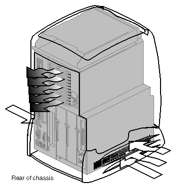
Figure 3-2 shows the airflow path in O2 systems. The white arrows show the air intake areas on both sides of the system. The side with three arrows has more airflow than the side with one arrow. The darker arrows show the air exhaust area at the rear of the system. Be sure that the location selected allows free flow of air to and from the areas shown.
O2 systems are designed for use in typical office computing environments: The air temperature should not fluctuate dramatically, air should circulate freely, and the location should be relatively dust free.
For information about selecting a physical location for an O2 system, see “Selecting a Location for an O2 System”.
Table 3-1 lists the physical specifications of the O2 chassis.
Table 3-1. O2 Chassis Physical Specifications
Dimensions |
|
|
Installed: | length | 11.5” (29.2 cm) |
In Packaging: | length | 20.2” (51.3 cm) |
Weight: | installed | 20 lbs (9.1 kg) |
Air Temperature: | operating | 50° to 95° F (10° to 35° C) |
Thermal Gradient: | operating | 18° F (10° C) per hour (maximum) |
Altitude: | operating | 10,000 ft (3,048 m) MSL (maximum) |
Relative Humidity: | operating | 10-80% (non-condensing) |
Vibration: | operating | 0.02”, 5-19Hz; 0.25 G, 19-100 Hz (maximum) |
Table 3-2 provides power consumption and required cooling capacity information for the O2 system. For formulas, descriptions, and general information about power and cooling, refer to “ Electrical Requirements” in Chapter 2 and “ Thermal Requirements” in Chapter 2.
| Caution: The power and cooling figures listed in Table 3-2 are maximums. Actual power and cooling requirements will vary, depending on configuration and load. Ask your SGI representative about particular configurations. |
Table 3-2. O2 Power and Cooling Specifications
Volts: |
| 100-120 volts AC, 1-phase |
Watts (from-the-wall): | maximum | 245 watts (see “Caution,” above) |
Power Factor: | minimum | 0.96 |
Total Harmonic Dist.: | at 120 volts | 5% maximum |
Inrush Current: | maximum | 40 amps |
Frequency: |
| 47-63 Hz |
Cooling Requirements: | maximum | 835 Btu/hr (0.07-ton AC load) (see
“Caution,” above) |
Airflow Volume: | maximum | 37 cfm (0.017 m3/s) |
See Appendix B, “Site Power and Power Cables”, for information about O2 chassis site-wiring and power cables.
An O2 system typically has a monitor, a keyboard, and a mouse. For more information, see “Monitors” in Appendix A, “Keyboards” in Appendix A, and “Mice” in Appendix A.
An O2 system may also have one or more external SCSI devices attached to it. For small SCSI devices, see “External SCSI Devices” in Appendix A. Also see information about Origin Vault systems in “Origin Vault Site Requirements” in Chapter 5.
Besides power cables and external peripherals (mentioned above), O2 systems are typically wired to network cables, serial and parallel devices, and so on. For details of the ports found on an O2 workstation, see the O2 Workstation Hardware Reference Guide.
See Appendix B, “Site Power and Power Cables”, for information about O2 chassis site-wiring and power cables.

