This chapter describes all the basic procedures needed to operate your SGI 2100 server. For more detailed information about specific components refer to the table of contents or index.
The design of the SGI 2100 provides customer maintenance access only to specific components within the system.
The following listed components must be serviced or replaced only by SGI trained and approved system support personnel:
The system midplane.
The system fan tray.
The node board(s).
The router board(s).
The XIO boards.
The power supply.
Other components and options within the system can be installed or replaced by the end user.
| Note: This product requires the use of external shielded cables in order to maintain compliance with Part 15 of the FCC rules. |
The operating procedures described in the following subsections are designed to ensure your safety and the integrity of your new system.
The SGI 2100 chassis can be configured for either 110-120 VAC or 220-240 VAC operation. The system requires alternating current (AC) service at specified voltage and current ratings for proper operation. The power supply is “auto ranging” and automatically adjusts for operation with either voltage range.
| Caution: The SGI 2100 requires the use of a 220-240 Volt electrical source whenever it is configured with more than four CPUs (or two node boards). Other factors may also apply; contact your service provider before upgrading your 110 Volt system. |
Verify that the correct AC line voltages are selected for any external peripheral you use with your system.
Before connecting or disconnecting any terminal, peripheral, or front-loading drive, be sure the module System Controller's (MSC) keyswitch is turned to standby and the system circuit breaker located on the back of the chassis is in the off position.
Read the following safety statements carefully before you install or remove any standard or optional components.
| Warning: Read the following safety information carefully before you install or remove standard or optional components. To avoid electric shock and/or a fire hazard, do not disassemble the chassis. No user-serviceable parts are located inside. |
This equipment is sensitive to damage from electrostatic discharge (ESD) caused by the buildup of electrical potential on clothing and other materials.
Before connecting or disconnecting any terminal, peripheral, or front-loading drive, be sure the system is powered off and the primary power source is disconnected.
Attach a ground strap to your wrist when working on the system.
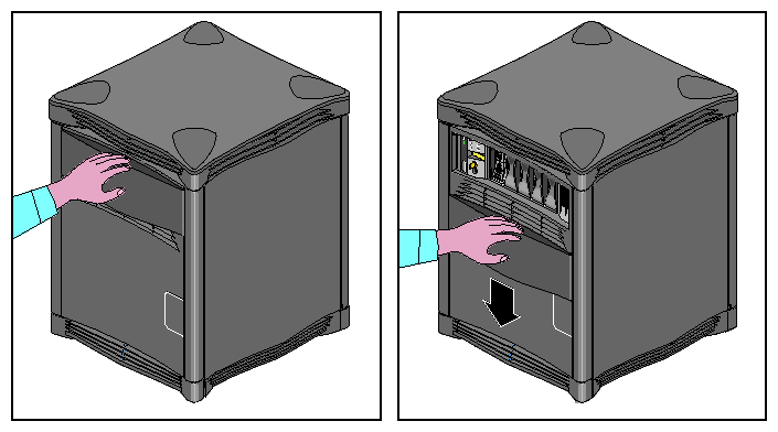
To access the drives and MSC you must open the front door of the system.
Use the following information to open or close the system's front sliding door panel:
Push down on the rectangular panel near the top on the front of the system.
Slide it downward until it locks in position. You should have clear access to the drives and the MSC interface panel (see Figure 3-1).
Close the panel by pushing down until you feel it release.
Let it slide back up into its original closed position.
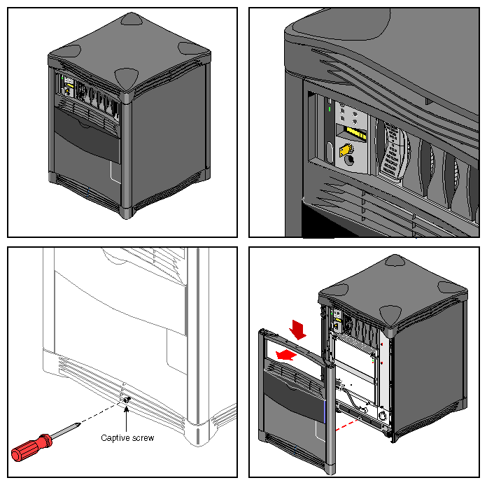
Under certain circumstances you may wish to remove some or all of the plastic covers from the SGI 2100 chassis. See “Sliding Open the Front Door Panel” if you need to access only the drives or the MSC front panel.
| Note: Do not operate the SGI 2100 with the plastic covers removed. Disruption to normal air flow patterns may cause system overheating. |
Use the following steps to remove the plastic covers from the SGI 2100:
Be sure that the system power is turned off and the power cable is disconnected from the back of the system.
Remove the plastic front panel cover by undoing the captive Phillips-head retaining screw located near the center of the bottom grill (see Figure 3-2).
Lower the panel approximately 0.15 inches (4 mm) and pull it forward off the chassis.
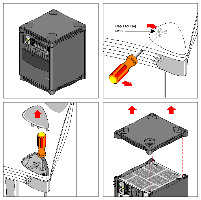
To remove the top cover you must first remove the four corner-positioned cover “caps” by using a screwdriver to release the latch for each one (see Figure 3-3).
Push the screwdriver through the upper grill and unlatch a cap, then lift the cap off. If you have trouble lifting the cap, press down on the outside corner of the cap until it pops up.
Remove the top plastic panel by undoing the captive screw under each cap and lifting the cover straight up off the chassis.

Note: It is highly unlikely that you will need to remove the rear plastic “bumper” cover or side panels. These three plastic covers are interconnected and somewhat difficult to remove. If you find it necessary, contact your service provider for assistance.
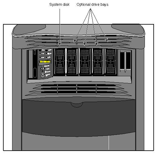
The SGI 2100 system comes standard with six drive bays. The first is located in the upper left sector on the front of the system and holds one 5.25-inch half-height CD-ROM drive. This single-ended drive bay is “hard wired” as SCSI ID 6 on the backplane. To the right of this bay is the MSC and then a bank of five 3.5-inch disk bays (see Figure 3-4).
The system disk is always SCSI ID 1 and is always installed in the disk drive bay directly to the right of the MSC. Each of the five disk drive bays is “hard wired” on the backplane to a single SCSI ID number (1-5). This prevents ever assigning the same SCSI ID to more than one drive installed in the SGI 2100.
| Caution: When you remove a drive be sure that you always put it back in the same bay that you removed it from. Placing the system disk in the wrong bay results in the system being unable to boot. Replacing a data disk in a different bay may cause file corruption, data loss, or other malfunction. |
See the information in Chapter 5 for details on removing, replacing, or installing drives.
| Caution: Use proper handling and storage procedures to avoid the loss of data and equipment. Do not remove disk drives while they are operating. Always power off the system before removing a drive. |
Be sure to use standard electrostatic discharge prevention precautions when removing, storing, transporting, or replacing drives.
All hard disk drives installed in the system must be Ultra SCSI or SCSI-2 compatible and use 80-pin single-connector assembly (SCA) drive sleds.
Use of external SCSI devices is supported through the BaseIO and optional XIO boards that install in the back of the system. See Chapter 5, “Installing and Replacing Customer Replaceable Units,” for additional information.
Your SGI 2100 system comes standard with an 8-pin 100-Mb-per-second Ethernet connector.
| Note: Always verify the type of signal being transmitted over your network cable before plugging in the connector. Some networks use a twisted-pair cabling system that carries AUI signals. These networks use an RJ-45 connector that is meant to be plugged into an IEEE 802.3 Transceiver unit. |
You can order optional SGI XIO boards for additional Ethernet connections.
Observe the following procedures when making Ethernet connections:
Identify the Ethernet drop intended for your system, and route it to the rear of the chassis. Repeat for any additional connections.
Plug in the Ethernet connector (make sure to properly secure the 8-pin connector).
Continue with any additional peripheral connections or installations.
Restart the system.
Use the following procedures to power on your new SGI 2100 system:
Make sure the power switches on all of the equipment are turned off.
Plug the power cord into each component. Make sure to connect the cords to grounded outlets only.
Turn on the power switches in the following order:
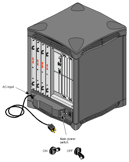
breaker switch located on the power-in panel on the back of the chassis
monitors, terminals or other video output devices
printer (if installed)
MSC key switch
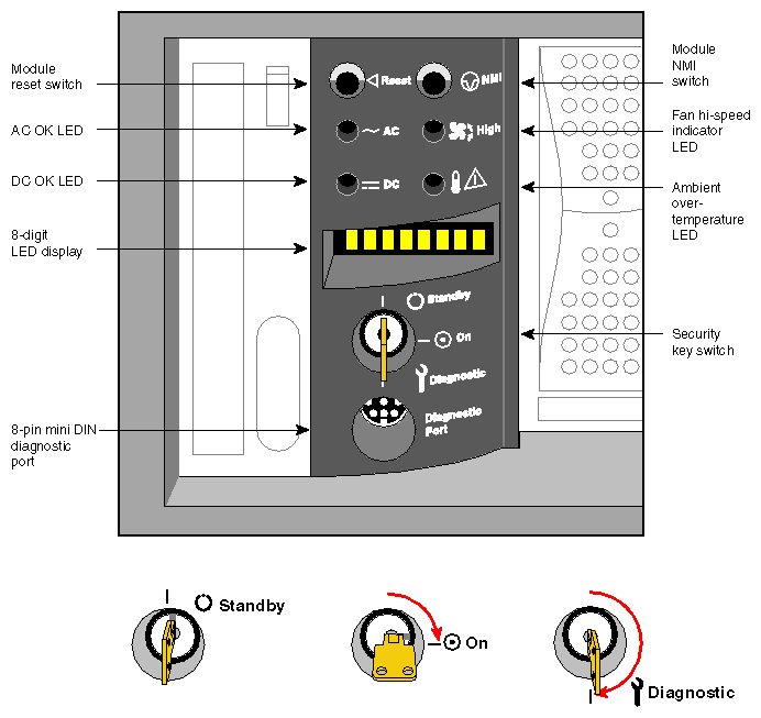
After you turn the MSC's switch to the On position, watch the LED panel for the [SYS OK] message. See Figure 3-5 for the keyswitch and other front panel switch locations.
| Note: Pushing either of the reset buttons during the boot process causes the system to abort the normal boot process. |
To better understand the MSC and its front panel interface, see Chapter 6, “Using the Module System Controller,” for more detailed information.
The SGI 2100 system should be completely powered off only for relocation, routine maintenance, or repair. Warn everyone who uses the system before you shut it down. Before beginning this procedure, log out and shut down the software using the instructions that follow:
To halt operating system activity and prepare the system for power off, become superuser and enter /etc/halt in a functional IRIX window. The /etc/halt command gracefully shuts down the system software and leaves you at the PROM monitor level. If you are remotely logged in to the system, you will be prompted before the shutdown procedure is executed.
Turn the MSC key switch to the standby position to eliminate power to the boards and peripherals.
Switch the system circuit breaker to the off position to eliminate all power to the midplane and power supply (see Figure 3-6 for the location of the switch).
Unplug the power cord from the socket if you need to cut off all electrical power to the system.
